Tuesday, February 16, 2010

Racycle Dating and Sharp Turns of Fortune on the Restoration Road

First, the Good News:
The Racycle Crank got an email a few months back from a reader in California who had recently become a Racyclist. His name is Blue Nelson, and he asked whether I could help him date the Racycle Roadster he had picked up from a local Craig’s List seller. The bike was complete and looked to be in pretty good nick, but Blue thought he’d like to restore it sometime.
By the absence of a pinch-bolt binder for the seat post, I figured the bike was built somewhere from 1901 to 1908. In 1901, the Miami Cycle and Manufacturing Company dispensed with using a pinch bolt through the frame to secure the seat post and instead equipped the entire Racycle range with seat posts (from the Standard Welding Company) that used an internal-expander bolt like that used for securing the handlebar stem. However, the switch was not permanent, and by 1908 most Racycle models were back to using the pinch bolt behind the seat post. Of the six different models in the 1908 Racycle range, only the Roadster Model 135 (second picture) still retained the internal-expander seat post.
It was impossible for me to define the build date any narrower than that because the bike had no model-number badge. This is not unusual. Some badges have been lost over the years, and some individual Racycles never had a model-number badge in the first place.
As to why the maker’s use of model-number badges was inconsistent, we can speculate that perhaps these badges were left off of bikes made at the end of the model year so that unsold machines wouldn’t suffer the stigma of being last-year’s inventory. Or maybe the maker simply ran out of badges at times. It’s always fun to speculate.
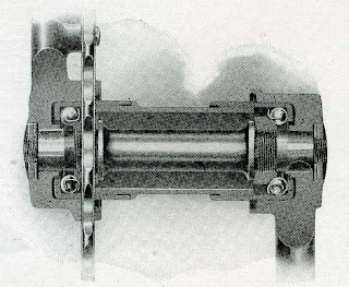
But then I noticed that Blue’s Racycle came with a bonus. It had the later “improved” crank hanger used from 1911. A crank hanger of the same vintage as the frame would have had a two-piece crank assembly with the two crank arms meeting in the centerline of the bottom bracket and working together by virtue of a set of three, coarse gear teeth (or "dogs") and held together with a draw bolt. This device is illustrated in cut-away view in the third picture. However, the later article uses a one-piece axle to which the crank arms are attached in more or less the modern way and work together by way of pins (1911 and 12) or Woodruff keys (1913 to ?) on the axle. The exploded view of the crank hanger (fourth picture) is from the 1913 catalog.
It’s fun to speculate about how the bike came to have the improved crank hanger. Was it installed to satisfy a warranty claim back in 1911, or it could have been installed to sell the bike on Craig’s List?
As an aside, the factory literature uses the term “improved” to describe the later crank design, but I have not tested the two designs for comparison. Although the later design seems sound (it came with a three-year guarantee!), “improved” will be only a descriptive name until we late arrivers can determine whether it really was better than the one it replaced. Below is a cut-away view of the "improved" crank hanger with one-piece axle as provided in 1913.

Bad News
Just last month, Blue emailed with bad news. In fact, it was horrible, tragic news. He had taken the bike apart to restore it, turned over numerous irreplaceable parts to an electroplater to have them renickeled, and then the electroplater disappeared. This was too much to believe. The ghost electroplater had made shop calls, so Blue didn’t even have an address to go to for answers, just a phone number. Blue finally gave up hope and started hunting for replacement parts. The last picture here is a "before" shot of the crank assembly on Blue's Racycle. Had it and the other parts truly vanished?
Good News
But now there is good news. The electroplater showed up again at Blue’s shop. He had all of Blue’s parts, and they were all re-nickeled as promised. The plater apologized for the delay, and for not returning phone calls. In fact, he was so sorry that he gave Blue his parts for free.
Of course, Blue is as happy as a clam at high tide. He is reassembling his Racycle, and I hope I can share photos of it here soon. Blue also gave the Racycle Crank some credit for his good fortune, saying that the next time his luck runs out, he’s going to email me and wait for things to magically improve! Seems to me that that’s stretching it a little, but I suppose it’s as likely as getting your parts plated for free.

Wednesday, February 10, 2010

Re-Tiring Procedure for Ordinary Bicycles (“High Wheelers”) and Wheel Toys

Have the tires worn thin on your 130-year-old ordinary bicycle? Does your pedal car need new shoes? Vintage tricycle got a flat? Here is one way to replace those old solid-rubber tires.
This is the first time I’ve offered a how-to article. In researching this very old process on the Web, I found only two detailed sources: they were from Dave Toppin and Rideable Bicycle Replicas. My process is a combination of both those I found, revised through trial and error. If you’re seriously considering replacing solid-rubber tires, you would do well also read the processes described by Mr. Toppin and RBR.
Summary Description
The solid-rubber tire material, which is almost solid except for a small-diameter hole through the center just big enough to slide in a 1/8-inch-diameter steel wire, is cut to length slightly oversize, and the wire is threaded through and pulled taught around the wheel while the ends of the rubber tire are held apart so that the wire can be brazed together.
Materials
  • Tire material from Holmes Wheel Shop.
  • PVC tubing cutter to achieve accurate, square cuts through the tire material.
  • 1/8” diameter (9 gauge) solid, steel wire from your local hardware or home-improvement store.
  • Fine sandpaper for removing corrosion-preventative coating from the wire where it will be brazed.
  • Silicone lubricant to help get the wire threaded into the rubber tire material.
  • Fabricated tool to keep ends of rubber tire material apart when tensioning the wire and brazing together its ends. See photos to get an idea of the one I made out of 1.5” steel tube and a couple of thick washers with slots cut in them. (The slots in the washers are necessary to allow the tool to be removed once you're done!)
  • Cable clamps to allow you to form a loop in each end of the wire so that it can be attached to a sturdy rack or other fixture and the come-along.
  • Come-along (hand winch) or other device to tension the wire.
  • Sturdy rack or other fixture to hook come-along to for tensioning wire. This may have to be able to withstand up to 150 or 200 lbs of pulling force depending on the size of the wheel you are re-tiring and the thickness of the tire. (Less pulling force may be sufficient for larger wheels). I used an over-built steel work bench. A towing ball on the back of your truck would work well for one end of your fixture.
  • Two pair of needle-nose Vice Grip pliers to clamp tensioned wire while excess wire is cut away and ends are brazed together.
  • Die grinder with cut-off wheel and rotary-file bit for cutting away excess wire and profiling the brazed joint so the tire material will close over the joint.
  • Oxy-acetylene torch kit and brazing rod.
  • Small piece of scrap sheet metal for use as a heat shield to protect the wheel when brazing.
  • Wet rag to quench the brazed joint once the job is done.
Procedure
Cut tire material oversize. Add an extra inch of length for each 10 inches of wheel diameter. For instance, if you have a 10-inch wheel, the appropriate length of tire material will be enough to go around and overlap 1 inch. If re-tiring a 50-inch wheel on an ordinary bicycle, the overlap will be 5 inches. Ensure the cut ends are smooth and square. Use a PVC tubing cutter and practice. For small diameter wheels, you might try to put a very slight bevel in the cut so that the length of tire along the wheel is very slightly less than the length along the outer diameter.
Cut wire to size and prepare the wire to be brazed. The length of wire necessary will be enough to go around the wheel, between the legs of your sturdy rack or other fixture, plus enough for a loop at each end. Cut the wire to size, lay it over your cut-to-size piece of tire material, and mark the approximate area along its length where the wire will protrude from the ends of the rubber. This is where the brazing will occur. Use fine sandpaper to remove the corrosion-preventative coating from the wire over an area about 5 inches either side of where you figure you’ll be brazing together the two ends. You can use a permanent marker to identify the ends of the area that you have prepared.
Install the wire. Use a file or die grinder to round off one end of the wire so you can feed it into the tire material. Depending on the length of the material, you might have to use silicone lube to get it through. The spray silicone lube will run down inside the tire and so might help with particularly large or stubborn cases. Feed the wire through the tool so that the two protruding sections of the wire cross one another. Wrap one end of the wire around a leg of your sturdy rack or other fixture, and secure it with one or two cable clamps. Put a loop in the other end that is big enough to put the come-along hook through, and secure it also with one or two cable clamps.
Tension the wire. Hook up the come-along, and fit the wheel into the tire. The wheel will have to be held in place with tape or light spring clamps until there is enough tension on the wire to compress the tire to hold the wheel. Consider laying towels or other soft material under the wheel to catch it in case there is a sudden loss of tension (wire breaks, fixture breaks, etc.). Crank the come-along until the tire material is snug against the wheel, then give it a little more additional tension to ensure that the ends will close over the gap and touch each other once the tool is removed. It should not need a lot more tension to ensure the joint closes when you are finished.
Prepare for brazing. Clamp the wire with needle-nose Vice Grip pliers at the point closest to where the wire emerges from the tire. Remove the come-along. Cut the wire with the die grinder so that there is about 1 inch of overlap. Bend the ends so that they touch along the length of their overlap. Clean the ends well, removing any silicone or other oils or dirt that might contaminate the brazed joint. Slip a suitably-sized piece of scrap sheet metal under the wire joint to act as a heat shield.
Braze ends. Use a small, hot, oxy-acetylene flame to braze together the two ends of the wire. Immediately quench the joint with a wet rag to prevent the hot wire from burning the rubber tire.
Finish the joint. Use a die grinder with a rotary-file bit to bevel the brazed joint along its length so that it is not substantially wider than the rest of the length of wire or the hole in the tire material. Use needle-nose pliers to twist the joint slightly so that it aligns straight with the rest of the wire. Clean out the grinder chips and any other debris, and remove the heat shield. Remove the tool by pulling it or levering it out with screwdrivers.
The compressed tire material should close over the brazed joint, with maybe a little help from you working the rubber to help it slip along the wheel and over the joint.
Roll away!
I hope that this post is helpful. This process worked for me, and I hope it'll work for you, too. As always, work safely. Fire and stored mechanical energy can be dangerous, so please try to anticipate what could go wrong before it does. I cannot be liable for things going wrong on your project.
If nothing else, my procedure sheds some light on how the Racycle Crank can turn the seemingly simple into an involved exercise. It might get simpler with practice.

Sunday, January 10, 2010

2009 Retrospective: Garton Delivery Cycle

2009 was a very unusual year for me—it was my first year of fatherhood. With a different set of responsibilities and priorities, it made sense to embark on a different sort of restoration project.
Enter one dilapidated old tricycle. It will be gift for my child, when he’s big enough. This particular item was an eBay find. Once I’d seen it I had to have it, as I’m a sucker for old trucks, and I had children on the brain at the time. Why not put the two together?
At first I thought it was a Hettrick Pedal Wagon, but then I deduced that it is a Garton Delivery Cycle. The chief piece of evidence in its identification was the name “Delivery Cycle” under a sloppy coat of green paint on either side of its wood pickup bed.
The Garton Toy Company of Sheboygan, Wisconsin, started business in 1879. Garton is probably most famous for its pedal cars, but they made a wide variety of wagons, scooters, and tricycles, too. I have not been able to determine when the first Delivery Cycles were produced, but they were certainly in production by 1950. The historical photo is from TricycleFetish.com.
The tricycle came from a nice man in Indiana who had bought it in Kentucky. It arrived carefully packaged, but from its poor condition it probably wasn’t worth the shipping charges. The first photos I took of it were after the restoration was well along, when it was beginning to look more worthwhile.
The fender took less than an hour to hammer straight, partly because it’s made of very thin steel, probably 22 gauge. To help it maintain its shape and to repair the fender’s rusted ends, I made up two doublers of 18 gauge steel, formed them to exactly match the fender contours, and brazed them in place on the underside at the front and back ends. The doublers made the flimsy fender rigid, and they took care of the material that had been eaten away by rust. A lot of balloon-tire bicycle fenders could probably be saved by similar treatment.
The fork was another victim of its own flimsiness. On any front-wheel-drive tricycle, the fork sees a lot of twisting torque as the pedals are pushed and the driver counters this with force at the handlebars to keep the machine going straight. You would expect the fork would be made strong to resist this constant twisting, but it was not. I suspect the tricycle makers all knew that their products had to last only a year or two. Thus, the fork steerer tube is not actually a tube at all. It’s just heavy-gauge rolled sheet metal brazed to the top of the fork; there’s still an open seam running the length of it. The fork itself is also just sheet steel formed in a U-channel—not a tube—and bent to fit over the front wheel.
Fork repairs were limited to welding up a tear at the fork bridge (such as it is in a single piece of formed sheet metal) and then welding shut the seam along the length of the fork’s steerer tube. I contemplated strengthening the fork itself, either by boxing closed the U-channel shape with welded-in sheet steel or by brazing steel rod into the recess of the U-channel. In the end I decided I’d cross that bridge another day when it actually starts to fail again from use.
Repair work on the handlebars focused on eliminating corrosion pitting so that the bars could be re-plated. The material appeared very thick, so I carefully ground down the handlebars with a small, right-angle die grinder. Then I used a fine-tooth flat file to laboriously block out the grinder marks so that the handlebars were true again (round and straight). The remaining file marks were taken out by hand sanding with #180 and #320-grit sandpaper. Then it was off to the electroplater’s shop.
Originally the frame tube was attached to the head tube by a big weld inside the head tube, such that on the outside there was still a seam showing where the two tubes joined. This joint had failed and someone had crudely reattached the parts with an arc welder by cobbling on big gobs of weld around the exterior of the joint. I ground out the arc weld and built up a decent-looking fillet weld using a MIG welder.
I also welded stops on the cranks and rear axles to limit the inward travel of the pedals and wheels. The original stops were just pinched and raised nubbins on the axles, but these had worn away almost entirely.
Painting was relatively straightforward, but the wheels took a lot of careful sanding of catalyzed filler primer to smooth out the effects of the surface rust. The colors are not quite true to the original Garton red, which was a metallic finish (with the metallic flake so fine that it looked almost like a candy apple red). Although I could have tried to match the original paint, remnants of which remained on the fork steerer tube, I could only guess at what paint designs and decals might have been on the frame, because it had already been thoroughly sandblasted long before I got it. Was the fender red or white? Was the head tube white? Were there contrasting pin stripes? Thus, I decided to go my own way with the paint scheme and colors.
Once the steel parts were painted, I set about making a new copy of the original wood box. The dimensions of the copy are precise down to the curved tops of the walls and the rabbets where the ends are inset into the sides. Even the nails are driven in at the exact same location as they were on the original, and the nail head diameter is identical to the originals. The only real deviation from the original box is that I used ¼-inch plywood for the floor instead of two 6-inch by ¼-inch oak planks nailed in side by side (“side by each” if you’re in Sheboygan, Wisconsin).
I painted the box with two coats of Rust-Oleum gloss black, which gave excellent results because it dried slowly enough that all of the brush marks flowed out. The Delivery Cycle would have originally had a red box to match the rest of the tricycle, but as I said I deviated somewhat from the original paint scheme. Red with a black box is the same color scheme that was on my first motor vehicle: a $50 1950 Dodge pickup. The purchase of that Dodge truck led to meeting my wife (a close friend of the seller’s sister), which ultimately led to this project.
The front wheel bearings I was able to clean out and reuse. They were made by a bearing manufacturer in Milwaukie. The rear wheels rode on Oilite bronze bushings of which little remained. They were each 7/16-inch inside diameter and ½-inch outside diameter. That’s right, the wall thickness was only 1/32 of an inch. Problem is, no one these days makes bushings that thin, so I bought bushings that were 7/16” ID by 9/16” OD and turned them down to fit.
But while doing all these other tasks, I was also working out how to replace the wire-secured solid-rubber tires. It took a long time to divine the process and sources for the materials. Basically, the solid-rubber tire material is almost solid except for a small-diameter hole through the center just big enough to slide a 1/8-inch-diameter steel wire. The tire material is cut to length slightly oversize, and the wire is threaded through and pulled taught around the wheel while the ends of the rubber tire are held apart so that the wire can be brazed together. The installation technique deserves its own post, but I’ll spare you unless someone requests it.
I bought tire material from Holmes Wheel Shop, an Ohio-based builder of wheels for Amish-style buggies. A come-along was used to tension the wire, and a tool of my own construction held apart the ends of the tire material while I brazed the wire together. It took a few attempts to work out the process, but in the end the results were great. If you want to know the details, leave a comment to this web post.
The last bridge to cross was painting the “Delivery Cycle” lettering on the sides of the box. I was able to take a pencil rubbing of the screened lettering off the original box. The rubbing was in turn scanned in to a computer, and I used Adobe Illustrator to trace it and convert the design to a digital file that I could take to a sign shop. At Fast Signs, they used the digital file to cut out self-adhesive vinyl lettering that I could use as a stencil.
For painting the lettering, I again chose Rust-Oleum for its slow-drying properties. An earlier attempt with spray paint had ended in failure when the paint came off with the stencil because it had dried too quickly to bond with the substrate paint. A little bit of yellow model paint added to the gloss white gave me the right tone of off-white. I puddled the paint on the stencil and used a razor blade to level it to match the thickness of the stencil. After about 15 minutes it had tacked up enough to hold itself together and not run, but it was still wet enough that I could peel up the stencil without taking the paint too. Simple!
I have extra “Delivery Cycle” stencils available for those who need them. In fact, they are both a stencil and the lettering too, so you could just stick on the vinyl letters if you wanted.
The license plate on the back came screwed to the original box on this tricycle. It had been painted over in green with the rest of box, so the plate must have been installed a long time ago—it might even be an original part. I scraped off the green paint to reveal black figures on a light yellow background. The colors are the same as those used on Wisconsin license plates in the early and middle 1940s, years that are consistent with the expected production date for this tricycle.
By a fair stretch, the Garton Delivery Cycle was the biggest project I took on in 2009. I hadn’t expected it to be such a challenge, but I like to learn new skills, and I’m happy with how it turned out. And, for once, I’m ahead of schedule. My son has at least another year and half of growing to do before he can reach the pedals.

Thursday, January 7, 2010

2009 Retrospective: 1966 Honda CB450 Super Sport


The 2009 holidays were a nice chance to re-connect with family, and not just a few asked what I’d been up to this past year. That recurring question got me thinking, and I realized that, although I accomplished less than I would have liked to, I was able to make some important improvements to a few ongoing projects.
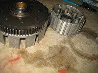
For instance I conquered the last of the Honda Black Bomber’s mechanical maladies: an intermittent but lingering shifting fault. The symptom was false neutrals, usually when shifting from first to second. I had thought that it was a problem with the shifting mechanism or the gearbox, but those seemed fine when I took them apart. Finally I noticed that the fault was worst in stop-and-go traffic but was rare when the clutch was cold. This suggested that the clutch plates were hanging up when they got hot instead of disengaging like they should. A close inspection of the clutch basket revealed indentations where the steel driven and driving plates had dug in to the aluminum parts of the clutch basket. The cure involved some very careful grinding to take out the indentations, and then I used a fine-tooth flat file to take out the grinder marks and get the clutch basket parts true again. This repair work seems to have eliminated the problem almost entirely—I still manage to flub up a shift on occasion, but it’s so rare I think it’s likely operator error.


Also the Honda finally got to wear a good set of fenders and side covers for the first time in about 40 years. In September 2007, I bought a rusty set of fenders from a fellow member of a local motorcycle club. I eliminated the rust (by a combination of sandblasting and phosphoric acid treatment) and hammered out the dents in short order, but then they sat for another year and a half. In June 2009, I finally got them painted. At the same time I painted a set of old steel side covers for the Honda. These I had gotten from different sources (right from one state, and left from another) thanks to eBay. Both were terribly rusted and dented, but I welded them up and carefully knocked out the dents. I treated the fenders and side covers with a phosphoric-acid solution to neutralize the rust and keep further corrosion from forming.

I love the look of straightened sheet metal. I wanted to install the parts in bare steel—with hammer marks and all—but I figured that would only be cool until I got caught in the rain. Since I’m lazy and did not want to take them off again to clean and paint them, I went ahead and painted them first before installing them.
The painted fenders are a departure from originality, but I’m not bothered. When introduced in mid 1965, the CB450 was issued with silver-painted fenders. It appears that Honda switched to chrome fenders in late 1966. My bike had chrome fenders when I got it, and I assume they were original, but a prior owner had lopped off the ends—a bob job. Perhaps the idea was to make the bike look less heavy, or custom chopped, or something. Now I’ve back-dated its styling a few months to the silver-painted fenders of 1965-66.

I think the painted fenders and side covers make it look much better than it did. I’ve never been a fan of chromed fenders on any motorcycle—I think chrome looks chintzy because it’s too easy. To my eye paint looks better, and a big part of paint’s good looks is knowledge of the effort involved and care taken. For the same reason I’m not a fan of powder coating motorcycles.